Before the manufacturing process can begin, a Bill of Materials, or BOM, needs to be developed to document all the components that will go into the final assembly.
Bill of Materials Definition
A Bill of Materials (BOM) is a document which describes the components of an assembly. This document should include the supplier(s) for each component, and the anticipated delivery schedule.
Bill of Materials Examples
There are a few different types of BOMs, each with a different use. The three most common are:
Single Level BOM – This Bill of Material describes a single assembly, often a “subassembly” that will be added to another assembly and used later in the process. The material listed identifies all the material needed to build that single assembly. Many times, the BOM lists documents that are needed for the assembly, e.g., Assembly Drawing, Assembly Procedure, Test Procedure(s) and similar items that are not part of the assembly but are needed to build the assembly. The Single Level BOM is most useful when building the product as it describes an assembly that a worker might build in one step.
Indented BOM– This Bill of Material describes an entire product. At the top level (level 0) is that main product with all packaging and ancillary material (e.g., Instructions for Use, power cord(s), required fittings). Each assembly on the top-level product is then “indented” to a sub-level so that all the material included in the shippable product is shown in one document, organized so that a reader can see which subassemblies are used on which assemblies. This is a recursive process, and it is normal that a product could have 5 to 8 levels of subassembly. The information contained on the BOM is the same as on a Single Level BOM; it is the organization and scope that is different. The Indented BOM is useful for engineering and management who need to have a complete view of the product. It is possible to generate an Indented BOM of a subassembly as well, if that gives a useful view of the assembly.
Summarized BOM – This Bill of Material lists all the components used in a product, but each individual item (e.g., an M6 x 14mm Stainless SHCS) appears only one time, with the quantity shown as the total of all the quantities on each assembly and subassembly. The Summarized BOM is useful for purchasing the material on the BOM. As such, it does not describe any one assembly since a single list covers all the assemblies. It details the entire heap of material necessary to build the full assembly. It does not typically contain documentation or subassemblies but focuses only on purchased material.
In the following tables, note these definitions:
- Line – this number simply assigns a number for the report. It makes it easy to identify the item.
- Level – this number identifies the sub-assembly structure. This BOM has 2 levels.
- PRI P/N – this is an identifier of the part that is unique to Product Resources.
- Rev – revision of the drawing
- Description – designers’ description of the part for reference.
- Qty – the quantity of the component on the subassembly.
- U/M – unit of measure (e.g., EA = each, IN = Inch, FT = foot, etc.)
- PLN – defines which group is responsible for the part. This is for Product Resources use.
- ENG = engineering, needs to be reviewed and released
- COT = commercial, off-the-shelf parts. Purchasing is responsible.
- CUT = custom designed parts, Purchasing is responsible.
- MFG = manufacturing is responsible, we are the manufacturer
- Manufacturer – if a COT part this identifies the company to buy it from
- Mfg P/N – this is the part number to buy
- Bbl – this is the number that ties this line/part number to a pointer on an assembly drawing.
Table 1 – Single Level BOM (below)
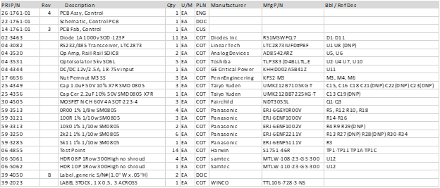
View Table 1 as a pdf – 26-1761-01 Single
Table 2 – Indented BOM (below)
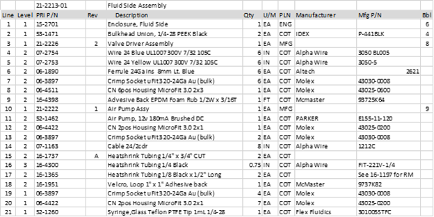
View Table 2 as a pdf – 21-2213-01 Indented
Bill of Materials Requirements
A BOM must have certain information to define the assembly.
1-Component Identification
Part Number. The part number is a unique identifier key for a system of organizing components. It is typically a number or an alphanumeric key. Since computers are often involved, the numbers don’t need to make sense to a person, they must just be unique. There is no harm in having an easy numbering system, but flexibility (and complexity) is usually required. Part numbers are assigned for every Item on the product, from the Top Assembly to the last screw.
Part Description. The description is important so that the people involved in the design and manufacture can better understand and identify the component. There are many ways to describe components, but the basic idea is to describe what the component is or what it does. Some examples are:
- Screw M4 x 14mm SHCS SS – this example has some encoding involved and if all the screws use this coding, it is easy to find them in a database. The encoding here is Size x Length, Type, Material. Product Resources part number for the part is: TH-20-40-14. These parts then appear in an inventory location with all the Threaded Hardware, Stainless Socket Head Cap Screws lined up by size. It makes them easy to find, which saves time.
- Valve, 3-way 100psi 24v – the important features of the valve should be listed so that it is easier to choose the valve in a list. There are many details that could be included e.g., port size, inlet/outlet fitting type and size, body material, wetted material, etc. It is up to the engineer to decide which are the important differentiators to include in the description and which should just be left for the datasheet. There is a bit of art involved is writing item descriptions.
- Bracket, Fan Mount – custom parts are more purpose-built than say, screws, so some descriptor showing what the part is designed to do is appropriate. Consider that you are looking for that fan mounting bracket on the bench. Will the description help you find it? Use the Part Number to confirm you have the correct one. Searching for parts by looking at labels with numbers on them is for a robot. Also, describe the parts for the assembler, not an engineer.
- Screw, Valve Mount – this is NOT a good example of naming a component unless this is a screw designed only for mounting a certain valve. It is not good style to show where the part goes in the description of the part. If it is a standard screw, you will end up with a bin of screws for each location where the screw is used rather than a bin of screws to use in many (appropriate) locations. You may also end up with hundreds of part numbers for essentially the same part and it will drive an inventory nightmare. In this example, the valve mount screw could require a specific parameter for mounting the valve (e.g., the screw head type). If you have two of the same size and length screws in front of you, but different heads, you could easily misuse the wrong screw. Describe the part for what it is and let the BOM reference designations show where it is used.
2-Quantity / Unit of Measure. The Quantity indicates how many or how much of a component or material is required for the Assembly. This seems obvious when detailing how many Valves are mounted on a Manifold but may be less obvious when describing how much thread-locking material is needed for an assembly with hardware.
The Unit of Measure is also important. The Valve to be mounted will likely be an EA (for Each) indicating a part that is counted (e.g., screws, machined parts, valves, connectors, etc.). Other types of products may need to be specified by:
- Meter, cm, in, etc. – wire, cable, tubing, double-sided tape, etc.
- mL, OZ, etc. – thread locker, potting compound, etc.
- A/R – a catch-all for “As Required” meaning engineering doesn’t know how much – you figure it out. As a practical matter, the builder would buy a tube, box, bottle, or whatever they thought appropriate. After a few builds it would be apparent, but there is the risk that you would run short and must scramble to buy more or end up with a stockroom full of bottles of expensive thread locker.
Be careful using parts that are defined by the box or similar packaging, say, a box of 100 screws. It must be clear that you need 6 screws, not 6 boxes of 100 screws. Consider the people who do the purchasing; when they are asked (by a computer) to buy 6 of a part number from a supplier, how do they know that you need 6 screws and not 600? Screws may seem like an easy thing to get right, but what about “1 EA, Epoxy, 2-part”? How many tubes would you buy – one tube for each unit you build, or will you only use 1mL per assembly?
3-Component Definition. The information required to define the component is also required when building a BOM for transfer to a Contract Manufacturer like Product Resources. Typically, a Manufacturer and Manufacturer’s Part Number are used for Commercial-off-the-shelf (COTS) parts, or a Purchase Specification Drawing are required for custom parts. See the chapter on Component Definition for additional details.
4-Assembly Reference. A bill of material, when “kitted” for assembly, will result in a group of parts placed on and around an assembly area. The parts are typically bagged and labeled with the part number which matches the part number on the BOM. The BOM tells you what material is present and in what quantity. An Assembly Drawing (or Assembly Procedure) is necessary to detail how the material is put together to form the Assembly. To do that, there needs to be a reference number on the Assembly Drawing which points to the part on the Assembly Drawing and links it to a specific Item on the BOM. Most manufacturing companies are using Resource Planning Software (ERP or MRP) systems to control material and those systems have the Assembly BOM in the Resource Planning database to facilitate the control of material flow. There are two main types of these designators:
- Bubble Numbers – parts on BOM for a mechanical assembly, e.g., Valve, 2-way, 12v, have a “Bubble Number” shown on the Assembly Drawing or Procedure, which also appears on the BOM. The Bubble Number is literally a number surrounded by a circle on the drawing (hence the “bubble”). Sometimes the BOM is also shown on the drawing and that is typical in many CAD packages like SolidWorks. It allows the worker to see the part on the drawing, trace the part to a part number, and then pick the part from the material present. Bubble numbers are references that are used for assembly but are of limited use beyond the factory floor. See Table 2 in the “Bbl” column for examples.
- Reference Designators – parts on a BOM for an electrical assembly like a Printed Circuit Board Assembly (PCBA), use “Reference Designators.” The reference designators are like bubble numbers but are tied back to a schematic representation of the electrical circuit. The reference designators are certainly used for the assembly of the board – usually by automated equipment but occasionally by manual assembly – but their usefulness extends to the initial design of the board schematic, and the service and repair of the PCBA. See Table 1 in the “Bbl / Ref Des” column for examples.
The 4 items above are the minimum information necessary on a Bill of Materials. There may be additional information that could be useful, e.g., Suppliers and Contact Information, Lead Times, Costs, Part Type (Document, Custom, COTS, Sheet Metal, Machined, Molded, etc.). Having this information will save time getting the material on order and orienting the manufacturer to the task. Without it, the manufacturer will need to take the time to open all the drawings and figure out part types, where to buy it, lead times, and other necessary data which is time intensive and costly.